


| Product Name | 90° Chain Disc Feed Line Corner | ||||||||||||||||||||||||
| Product Image | 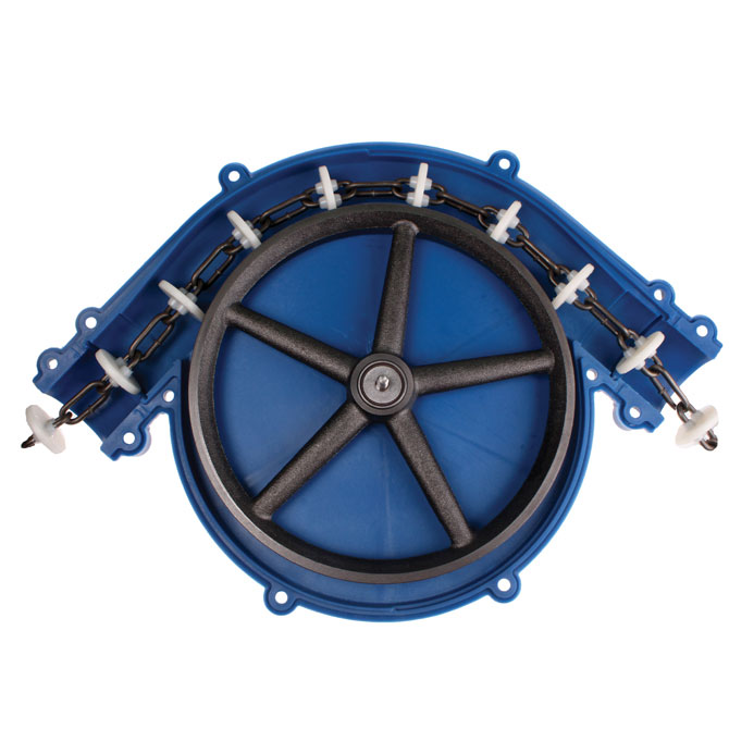 |
||||||||||||||||||||||||
| Product Overview |
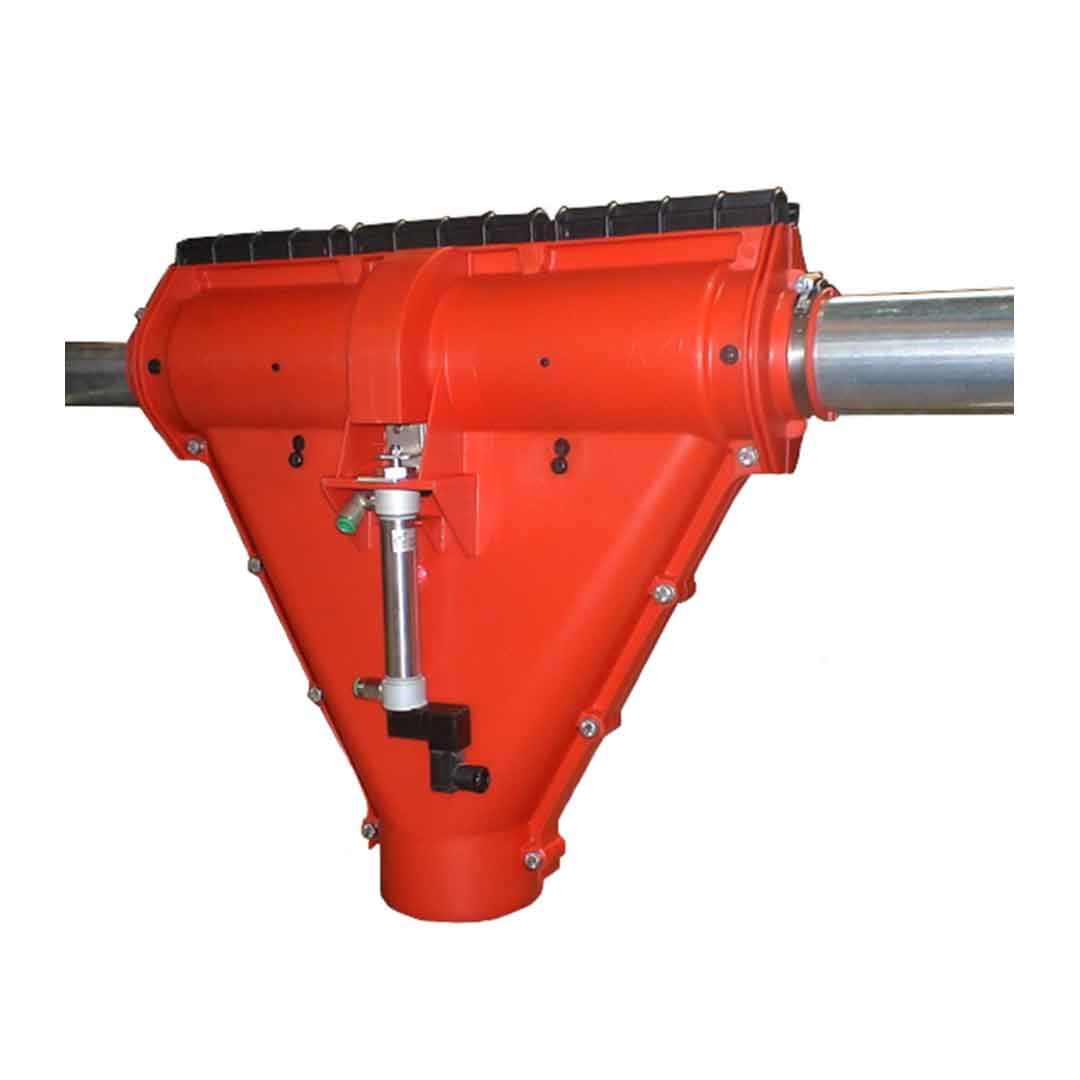
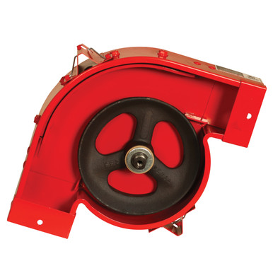
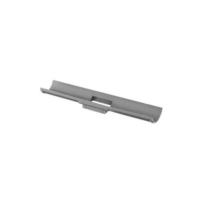
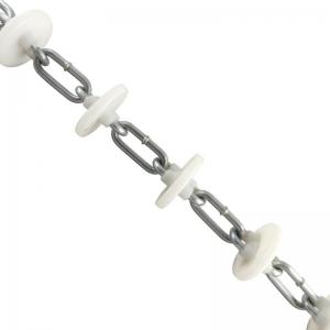
The 90° Chain Disc Feed Line Corner is a directional component designed for automatic chain-disc feeding systems used in commercial pig farms and other livestock facilities. It allows the feed conveying circuit to change direction by 90 degrees while maintaining smooth movement of the chain and carrier discs. Inside the corner housing, a large-radius guide wheel supports the chain as it travels around the bend. Correct wheel geometry helps reduce friction, chain tension and wear on chain links while minimizing the risk of feed accumulation inside the corner. The component is suitable for horizontal and vertical direction changes in enclosed feed distribution circuits and can be integrated with feed pipes, drive units, silo outlets, drop feeders and automatic control systems. For pig farm construction and livestock equipment projects, corner quantity, pipe diameter, chain specification and mounting arrangement can be selected according to feed-line length, barn layout and conveying capacity requirements. |
||||||||||||||||||||||||
| Key Features |
|
||||||||||||||||||||||||
| Structural Components |
|
||||||||||||||||||||||||
| Working Principle |
The chain fitted with carrier discs enters the corner through the feed pipe and engages with the guide wheel. As the drive unit pulls the chain, the wheel rotates and redirects the chain through a controlled 90-degree arc. Feed carried between successive discs follows the enclosed path around the corner and continues into the next pipe section. The wheel supports the chain throughout the bend, helping prevent excessive rubbing against the housing. Because every corner adds mechanical resistance to a chain-disc circuit, the number and position of corners should be included when calculating total system length, motor power and chain tension. |
||||||||||||||||||||||||
| Technical Specifications |
|
||||||||||||||||||||||||
| Applications |
|
||||||||||||||||||||||||
| Customization Options |
|
||||||||||||||||||||||||
| Installation & Maintenance |
Layout Planning: Determine each required direction change during feed-line design. Excessive corner quantity should be avoided because every corner increases total chain resistance. Pipe Alignment: Straight feed pipes should align accurately with the corner inlet and outlet. Misalignment can increase chain wear and mechanical loading. Structural Support: The corner housing should be securely fixed to suitable brackets, walls or steel structure building members so that pipe loads are not transferred unnecessarily to the corner assembly. Chain Installation: Confirm that the chain and carrier discs engage correctly with the guide wheel and move freely before commissioning the complete circuit. Inspection: Periodically inspect the guide wheel, bearings, chain, carrier discs, housing and pipe connections for abnormal wear or looseness. Cleaning: Open the service cover where provided and remove feed residue or foreign material according to the farm maintenance schedule. |
||||||||||||||||||||||||
| Project Applications |
In commercial pig farm projects, 90° corners are commonly installed where the chain-disc feed line must pass around livestock houses, structural columns, service corridors or other farm equipment. Corners can also be positioned to transfer the feed line between horizontal and vertical sections, allowing a feed circuit to run from external storage silos into livestock buildings and then distribute feed to multiple rows of feeders. Final corner quantity should be evaluated together with total conveying length, feed delivery capacity, drive-unit power and chain tension. Reference PigTek system specifications indicate that allowable line length decreases as additional corners are added to the circuit. |
||||||||||||||||||||||||
| Product FAQ |
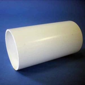
Q: What is the function of a 90° chain disc feed line corner? A: It redirects the chain and carrier discs through a 90-degree change in direction while maintaining an enclosed feed conveying path. Q: Can the corner be installed vertically? A: Suitable chain-disc corner assemblies can be used for horizontal or vertical direction changes when correctly supported and integrated into the system layout. Q: Does adding more corners affect the feed line? A: Yes. Every additional corner increases mechanical resistance and should be included in calculations for maximum conveying length, chain tension and drive power. Q: What pipe size is available? A: Pipe size depends on the selected chain-disc system. Reference systems include approximately 56 mm outside diameter, while 60 mm, 63 mm and other project-specific sizes can also be supplied. Q: Can the corner be opened for cleaning? A: Yes. Suitable designs use removable or quick-release covers to simplify inspection, cleaning and maintenance. Q: Can it be used with an existing chain-disc feeding system? A: Yes, provided that pipe diameter, chain dimensions, carrier-disc spacing and mechanical interfaces are compatible with the existing system. Q: What information is needed for selection? A: Please provide pipe outside diameter, chain size, carrier-disc diameter, required installation orientation, number of corners, approximate total circuit length and feed conveying capacity. |
||||||||||||||||||||||||
| Product Gallery |
|
- Home
-
Products
- Pig Farming Equipment
- Cattle Farming Equipment
- Sheep & Goat Farming Equipment
- Poultry Farming Equipment
- Feeding & Drinking Systems
- Veterinary & Breeding Equipment
- Testing & Diagnostic Equipment
- Cleaning & Biosecurity Equipment
- Climate Control Equipment
- Livestock Weighing Equipment
- Manure & Waste Management
- Farm Transport & Handling
-
Solutions
- Pig Farm Solutions
- Dairy Farm Solutions
- Beef Cattle Farm Solutions
- Sheep & Goat Farm Solutions
- Layer Farm Solutions
- Broiler Farm Solutions
- Feeding & Drinking System Solutions
- Climate Control Solutions
- Biosecurity & Disinfection Solutions
- Manure & Waste Management
- Smart Farming Solutions
- Farm Renovation and Upgrade Solutions
- Partners
- Projects
- Resources
- News
- About Us
- Contact


Comments & Inquiries
Leave your questions or requirements below. We will reply as soon as possible.