


| Product Name | High-Viscosity Liquid Feed Hopper Pump | ||||||||||||||||||||||||||||||
| Product Image |  |
||||||||||||||||||||||||||||||
| Product Overview |
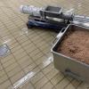
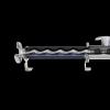
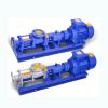
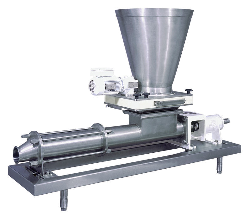
The High-Viscosity Liquid Feed Hopper Pump is a hopper-fed progressive cavity pump developed for transferring thick, low-flowability and solids-containing feed mixtures in automated livestock feeding systems. Its open inlet hopper incorporates a feed screw that continuously moves viscous material toward the pumping elements. A compression section helps improve filling of the rotor-stator cavities, making the pump suitable for materials that cannot reliably enter a conventional suction pump by gravity alone. The progressive cavity pumping principle provides controlled, low-pulsation and relatively low-shear transfer. This is useful for liquid feed recipes containing cereal mash, wet feed ingredients, food-industry by-products, fibrous fractions or other pumpable mixtures where consistent delivery and gentle handling are important. The pump can be integrated into commercial pig farm feed kitchens together with mixing tanks, intermediate tanks, weighing systems, pipelines, valves and automatic feeding controllers. Pump size, hopper geometry, materials, drive configuration and connection standards can be selected according to project requirements. |
||||||||||||||||||||||||||||||
| Key Features |
|
||||||||||||||||||||||||||||||
| Structural Components |
|
||||||||||||||||||||||||||||||
| Working Principle |
High-viscosity feed enters the open hopper from a mixing tank, ingredient preparation system or other upstream equipment. The integrated screw conveyor moves the material toward the compression section instead of relying only on gravity flow. The compression zone promotes reliable filling of the progressive cavity pumping chamber. The motor-driven rotor then rotates eccentrically inside the elastomer stator, creating a sequence of sealed cavities. As the rotor turns, these cavities move continuously from the inlet toward the discharge side, transporting the feed at a controlled volumetric rate. This operating principle generates relatively low pulsation and is suitable for viscous, shear-sensitive and solids-containing media. Pump output can be coordinated with tank weighing, valve positioning and feeding schedules through the central liquid-feeding controller, allowing automated transfer between feed preparation and distribution stages. |
||||||||||||||||||||||||||||||
| Technical Specifications |
|
||||||||||||||||||||||||||||||
| Applications |
|
||||||||||||||||||||||||||||||
| Customization Options |
|
||||||||||||||||||||||||||||||
| Installation & Maintenance |
Installation Position: Install the pump close to the mixing or intermediate tank wherever practical. The hopper should receive feed freely from the upstream equipment without unnecessary restrictions. Foundation and Alignment: The base frame should be mounted on a level concrete foundation or engineered steel support. Correct alignment helps protect the drive, shaft and pumping components from unnecessary mechanical stress. Pipeline Design: Discharge pipe diameter, length, elevation and number of bends should be considered during pump selection. Excessive pipeline resistance can increase operating pressure and component wear. Dry-Running Protection: Progressive cavity pumps should not be operated without suitable product lubrication in the stator. Level monitoring or other dry-running protection is recommended for automated installations. Overpressure Protection: The discharge side should incorporate suitable pressure monitoring or protection according to the process design. Cleaning: The hopper, screw, rotor-stator section and feed-contact surfaces should be cleaned according to the farm hygiene program. Hygienic versions can be configured for suitable CIP or other cleaning procedures. Routine Maintenance: Periodically inspect the rotor, stator, coupling components, shaft seal, feed screw, gearbox and bearings. Wear intervals depend on feed abrasiveness, operating pressure, speed and daily running time. |
||||||||||||||||||||||||||||||
| Project Applications |
In a commercial finishing farm, the hopper pump can be positioned beneath or beside a liquid feed preparation tank to transfer high-dry-matter recipes into the distribution circuit. The feed screw assists mixtures that do not flow readily into a conventional pump inlet. For farms using brewery, dairy, cereal-processing or other suitable agricultural by-products, the pump can be incorporated into an ingredient receiving or intermediate transfer system before final recipe mixing. Large livestock projects can combine multiple pumps with weighed tanks, automated valves and centralized PLC control. Final equipment selection should be based on feed viscosity, solids content, particle characteristics, required capacity, pipeline pressure loss and cleaning requirements. |
||||||||||||||||||||||||||||||
| Product FAQ |
Q: Why use a hopper pump instead of a standard centrifugal pump? A: High-viscosity or poorly flowing feed may not enter a centrifugal pump reliably. The hopper and feed screw actively move the material into the progressive cavity pumping section. Q: What type of pump is used inside this system? A: The main pumping section uses the progressive cavity principle, with a rotating helical rotor operating inside a matching elastomer stator. Q: Can it pump feed containing solid particles? A: Suitable configurations can handle pumpable mixtures containing suspended or soft solids. Maximum particle characteristics should be confirmed for each project. Q: Is the pump suitable for very thick feed mixtures? A: Yes. The open hopper, feed screw and compression zone are specifically suited to viscous materials with limited natural flowability. Q: Can the pumping rate be adjusted? A: Yes. Progressive cavity pump capacity is closely related to rotational speed, so suitable systems can use variable-frequency control for adjustable flow. Q: Is a hygienic version available? A: Yes. Hygienic configurations can use stainless steel feed-contact components, appropriate joints, sanitary connections and cleaning provisions according to project requirements. Q: Can the pump be connected to an automatic liquid feeding controller? A: Yes. The motor, frequency converter, valves and sensors can be integrated with a compatible PLC or livestock liquid-feeding computer. Q: What information is required for pump selection? A: Please provide feed ingredients, approximate viscosity or dry-matter content, solid particle characteristics, required flow rate, pipeline length and elevation, required discharge pressure, operating temperature, cleaning requirements and electrical supply. |
||||||||||||||||||||||||||||||
| Product Gallery |
|
- Home
-
Products
- Pig Farming Equipment
- Cattle Farming Equipment
- Sheep & Goat Farming Equipment
- Poultry Farming Equipment
- Feeding & Drinking Systems
- Veterinary & Breeding Equipment
- Testing & Diagnostic Equipment
- Cleaning & Biosecurity Equipment
- Climate Control Equipment
- Livestock Weighing Equipment
- Manure & Waste Management
- Farm Transport & Handling
-
Solutions
- Pig Farm Solutions
- Dairy Farm Solutions
- Beef Cattle Farm Solutions
- Sheep & Goat Farm Solutions
- Layer Farm Solutions
- Broiler Farm Solutions
- Feeding & Drinking System Solutions
- Climate Control Solutions
- Biosecurity & Disinfection Solutions
- Manure & Waste Management
- Smart Farming Solutions
- Farm Renovation and Upgrade Solutions
- Partners
- Projects
- Resources
- News
- About Us
- Contact



Comments & Inquiries
Leave your questions or requirements below. We will reply as soon as possible.