

| Product Name | Variable-Speed Feed Line Drive Unit | ||||||||||||||||||||||||
| Product Image | 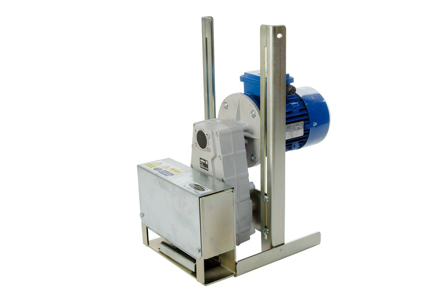 |
||||||||||||||||||||||||
| Product Overview |
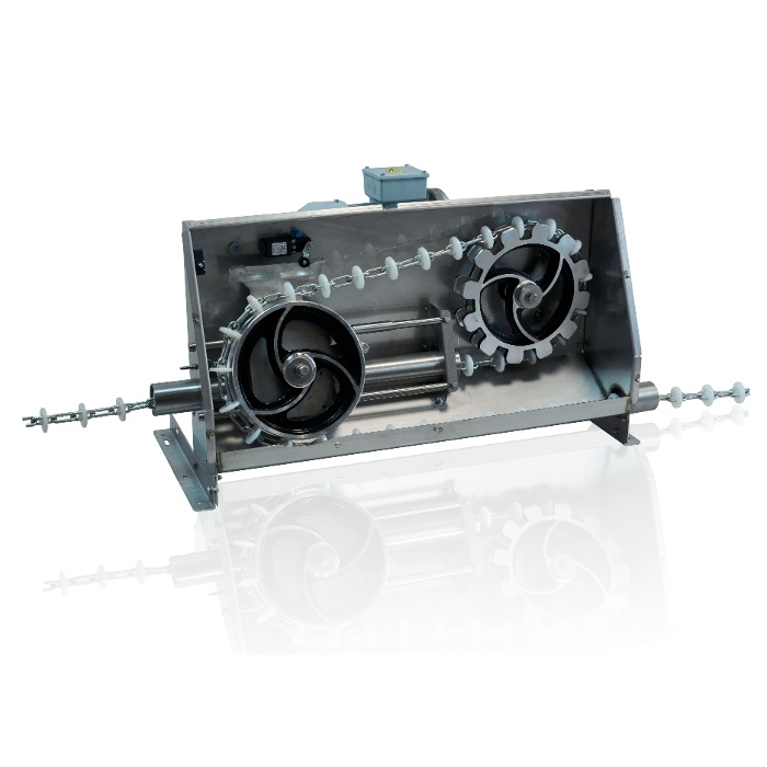
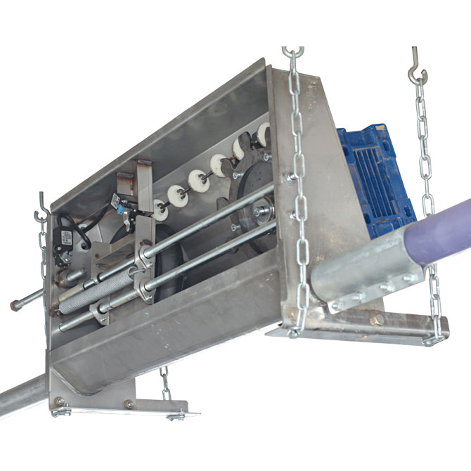
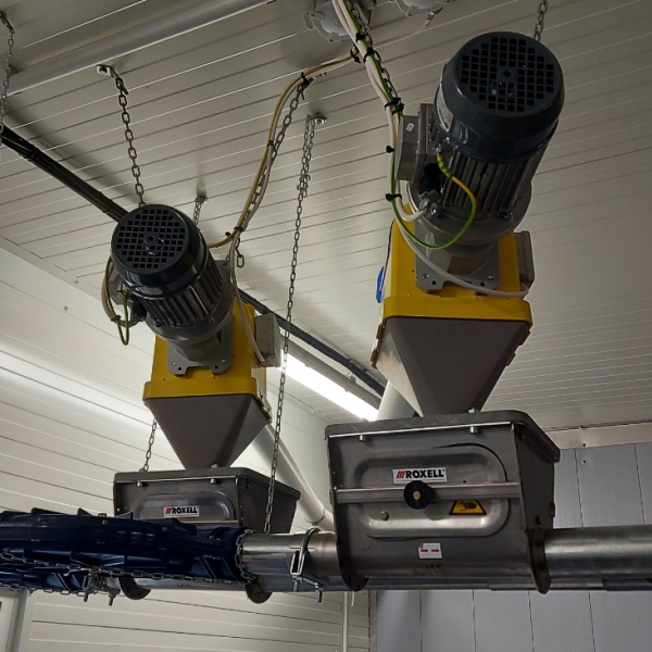
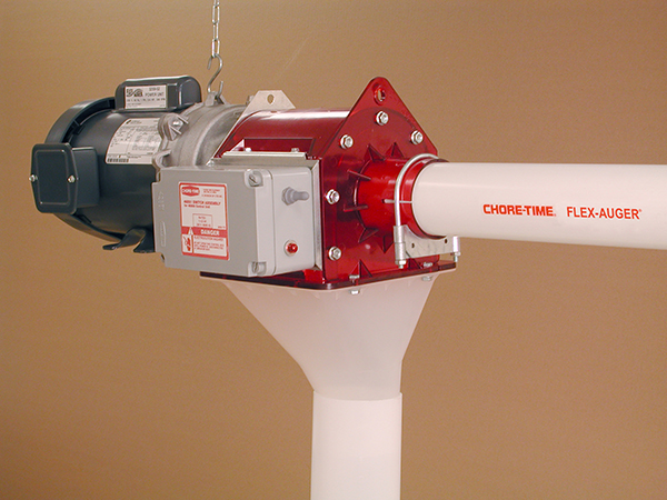
The Variable-Speed Feed Line Drive Unit is a motor-and-gearbox assembly designed to power automatic chain feeding systems in commercial poultry houses. It provides the controlled mechanical force required to circulate the feed chain through the trough system and distribute feed rapidly and consistently to birds throughout the house. Variable or selectable operating speed allows the feeding line to be adapted to different flock ages, feeding programs, chain lengths and management strategies. Depending on the project, speed adjustment can be achieved through a suitable motor configuration, transmission arrangement or frequency inverter. The unit is suitable for broiler breeder, pullet and layer feeding projects and can be incorporated into new poultry farm construction, livestock equipment renovation and steel structure building projects. Big Dutchman chain feeding systems are available with different conveying speeds according to production requirements. :contentReference[oaicite:1]{index=1} |
||||||||||||||||||||||||
| Key Features |
|
||||||||||||||||||||||||
| Structural Components |
|
||||||||||||||||||||||||
| Working Principle |
When a feeding cycle starts, the electric motor rotates the gearbox input shaft. The gearbox reduces rotational speed and increases torque before transmitting power to the feed-chain drive wheel. The drive wheel engages the chain and pulls it continuously through the feeding trough. As the chain travels around the circuit, it carries and distributes feed from the hopper along the complete feeding line. The operating speed can be selected or adjusted according to the drive configuration. Faster chain movement can help place feed rapidly around the circuit, while lower speeds may be selected for specific management programs or system requirements. A chain feeder drive typically combines an electric motor, gearbox and drive wheel. Protection devices can interrupt transmission when the chain is obstructed, helping reduce the risk of mechanical damage. :contentReference[oaicite:2]{index=2} |
||||||||||||||||||||||||
| Technical Specifications |
|
||||||||||||||||||||||||
| Applications |
|
||||||||||||||||||||||||
| Customization Options |
|
||||||||||||||||||||||||
| Installation & Maintenance |
Drive Position: Install the unit at the designated position in the chain feeder circuit with sufficient space for inspection, chain adjustment and motor maintenance. Mechanical Alignment: The drive sprocket must be correctly aligned with the feeding trough and chain. Misalignment can increase wear and operating resistance. Chain Setup: Feed chain tension should be adjusted according to the complete circuit length and manufacturer's installation requirements. Speed Configuration: Confirm motor rotation direction, gearbox output speed and controller settings before the first feeding cycle. Safety Commissioning: Protective covers, overload devices, emergency stopping functions and electrical protection should be checked before operation. Routine Maintenance: Regularly inspect the motor, gearbox, drive sprocket, feed chain, bearings, fasteners and protective devices. Gearbox lubrication and electrical maintenance should follow the requirements of the selected components. |
||||||||||||||||||||||||
| Project Applications |
In a typical broiler breeder project, the drive unit circulates the chain around a closed trough loop so that feed is delivered rapidly throughout the poultry house. Fast and uniform feed distribution is particularly important in restricted-feeding programs where birds should gain access to feed within a short period. For larger poultry buildings, drive selection should consider the complete chain length, number of corners, quantity of feed in the trough and required distribution speed. Additional drive capacity may be required for longer circuits. :contentReference[oaicite:3]{index=3} |
||||||||||||||||||||||||
| Product FAQ |
Q: Why is feed-chain speed important in breeder management? A: Rapid and uniform feed distribution helps reduce differences in feeding access between birds. The appropriate speed should be selected according to house size, flock management and feeding program. Q: Can the drive speed be adjusted? A: Yes. Adjustable or selectable speed configurations can be provided using a suitable motor, gearbox, multi-speed arrangement or frequency inverter. Q: What chain speeds are commonly used? A: Reference poultry chain feeding systems are available with conveying speeds such as 12, 18 and 36 m/min. The required speed should be selected for the actual feeding system rather than treated as a universal specification. :contentReference[oaicite:4]{index=4} Q: How is the correct motor power selected? A: Motor and gearbox sizing depends on total chain length, feeding speed, trough load, number of corners, friction and other system design factors. Q: Can the drive unit be used for an existing poultry feeding line? A: Retrofit installation is possible when the drive wheel, chain dimensions, trough arrangement, mounting position and electrical requirements are compatible. Q: Can it operate with an automatic feeding controller? A: Yes. The drive motor can be connected to compatible timers, relays, control cabinets or variable-frequency drives according to the project design. Q: What information is required for quotation? A: Please provide poultry type, feeding-line layout, total chain length, number of corners, required feed-chain speed, local voltage and frequency, preferred control method and details of the existing feeding system if applicable. |
||||||||||||||||||||||||
| Product Gallery |
|
- Home
-
Products
- Pig Farming Equipment
- Cattle Farming Equipment
- Sheep & Goat Farming Equipment
- Poultry Farming Equipment
- Feeding & Drinking Systems
- Veterinary & Breeding Equipment
- Testing & Diagnostic Equipment
- Cleaning & Biosecurity Equipment
- Climate Control Equipment
- Livestock Weighing Equipment
- Manure & Waste Management
- Farm Transport & Handling
-
Solutions
- Pig Farm Solutions
- Dairy Farm Solutions
- Beef Cattle Farm Solutions
- Sheep & Goat Farm Solutions
- Layer Farm Solutions
- Broiler Farm Solutions
- Feeding & Drinking System Solutions
- Climate Control Solutions
- Biosecurity & Disinfection Solutions
- Manure & Waste Management
- Smart Farming Solutions
- Farm Renovation and Upgrade Solutions
- Partners
- Projects
- Resources
- News
- About Us
- Contact

Comments & Inquiries
Leave your questions or requirements below. We will reply as soon as possible.