

| Product Name | Belt-Drive Auger Feed Unit | ||||||||||||||||||||||||||||
| Product Image |  |
||||||||||||||||||||||||||||
| Product Overview |
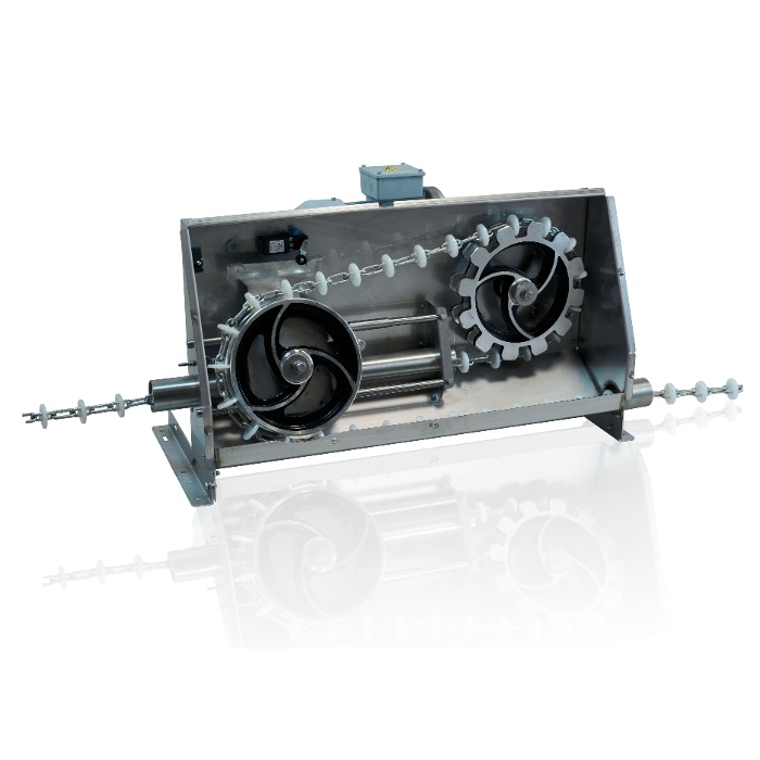
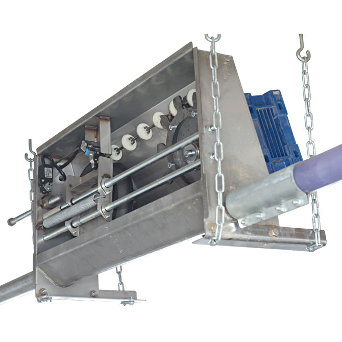
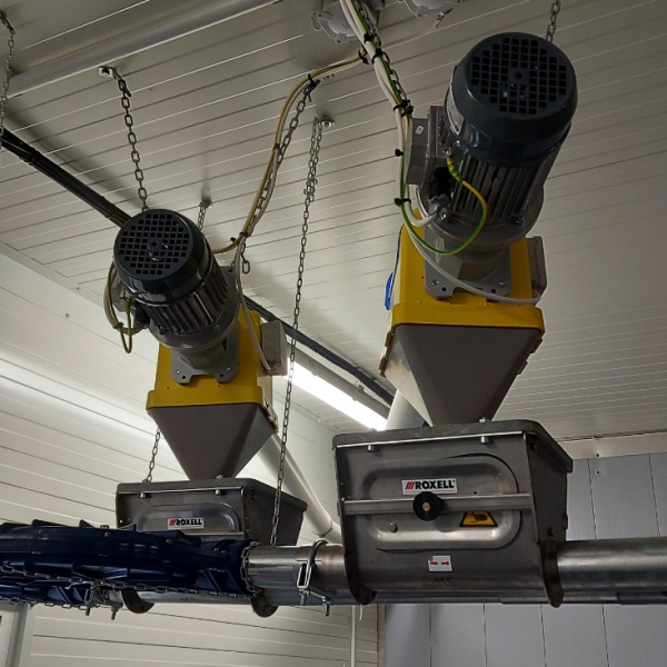
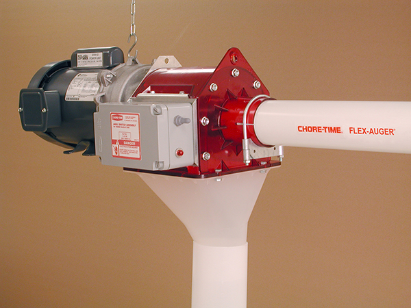
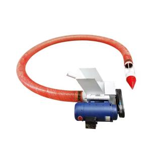
The Belt-Drive Auger Feed Unit is a mechanical power assembly designed to drive flexible or compatible rigid augers in automatic livestock feed conveying systems. Instead of connecting the electric motor directly to the auger through an integrated gearhead, the belt-drive configuration transfers motor power through matched pulleys and V-belts to the auger drive shaft. The unit is suitable for feed transport from silos, feed bins or intermediate hoppers to automatic feeding lines in commercial pig farms, poultry houses and other livestock production facilities. Belt-driven auger arrangements are widely used where accessible mechanical transmission, flexible motor selection and convenient serviceability are required. For new pig farm construction or livestock house renovation, the motor power, pulley ratio, auger diameter, line length, feed characteristics and electrical configuration can be selected according to project requirements. The drive unit can also be integrated with level switches and feed line controls for automatic start and stop operation. |
||||||||||||||||||||||||||||
| Key Features |
|
||||||||||||||||||||||||||||
| Structural Components |
|
||||||||||||||||||||||||||||
| Working Principle |
When the feed control system calls for feed, the electric motor starts and rotates the motor pulley. One or more V-belts transfer this rotation to the larger driven sheave connected to the auger drive shaft. The drive shaft rotates the spiral auger inside the feed tube. As the auger turns, dry feed is moved from the silo or hopper through the conveying pipe toward livestock house feeders, distribution hoppers or feed drops. The pulley ratio determines the relationship between motor speed and auger speed. Correct speed selection is important for maintaining suitable conveying performance and reducing unnecessary mechanical loading on the auger system. A level switch or control device at the downstream feed point can stop the motor when the feeding line is filled. The unit restarts automatically when feed demand is detected, depending on the selected control configuration. |
||||||||||||||||||||||||||||
| Technical Specifications |
|
||||||||||||||||||||||||||||
| Applications |
|
||||||||||||||||||||||||||||
| Customization Options |
|
||||||||||||||||||||||||||||
| Installation & Maintenance |
Drive Unit Position: Install the power unit at the designed end of the auger line or at the specified drive position. The supporting structure must be capable of carrying the operating load of the motor, transmission assembly and feed line. Pulley Alignment: The motor pulley and driven sheave must be correctly aligned. Incorrect alignment can increase belt wear, vibration and bearing load. Belt Adjustment: Adjust the motor mounting position until suitable belt tension is achieved. Excessively loose belts may slip, while excessive tension may increase bearing and shaft loads. Safety Guard: Install and secure the complete belt guard before operating the feed line. The drive should never be operated with exposed rotating pulleys or belts. Auger Connection: Insert and secure the conveying tube through the appropriate tube adapter and clamp. Confirm that the auger is properly connected to the drive shaft or arbor. Electrical Commissioning: Verify motor rotation direction, overload protection, sensor operation and automatic stop functions before normal feeding operation. Routine Maintenance: Regularly inspect belt tension, pulley alignment, belt condition, bearings, shaft connections, mounting bolts, guards, electrical cables and feed level controls. Replace worn belts as a matched set when required. |
||||||||||||||||||||||||||||
| Project Applications |
In a typical commercial livestock project, the belt-drive unit is positioned at the end of a flexible auger line that transports feed from an outdoor silo or bulk feed bin into the animal house. Feed travels inside enclosed tubing and is discharged through outlets into feeding hoppers or automatic feeders. For larger pig farms, separate auger systems can be configured for sow houses, nursery houses and finishing buildings. Motor size and belt transmission should be selected according to the actual conveying distance, number of bends, feed characteristics and required delivery capacity. During pig farm construction or steel structure building design, sufficient mounting space and service access should be reserved around the drive unit to allow belt adjustment, motor replacement and routine inspection. |
||||||||||||||||||||||||||||
| Product FAQ |
Q: What is the difference between a belt-drive and direct-drive auger unit? A: A belt-drive unit transfers motor power through pulleys and one or more V-belts, while a direct-drive system normally uses a motor and gear reducer connected directly to the auger drive. Belt-driven designs provide accessible transmission components and allow pulley ratios to be selected for the required operating speed. Q: Is the motor included with the drive unit? A: The supply scope is customizable. A belt-drive assembly can be supplied with or without an electric motor according to project requirements. Q: How is the correct motor power selected? A: Motor selection depends on auger diameter, conveying distance, number of bends, feed characteristics, required delivery rate and electrical supply conditions. Q: Can the belt-drive unit operate automatically? A: Yes. The drive can be connected to compatible level switches, feed sensors, control pans, timers or automatic feed control systems. Q: Can the pulley ratio be customized? A: Yes. Pulley and sheave dimensions can be configured according to the required motor and auger operating speeds within the engineering limits of the system. Q: Is the unit suitable for existing feed lines? A: Retrofit installation is possible when the auger size, tube connection, shaft arrangement, motor specification and supporting structure are compatible. Q: What maintenance is required for the belt transmission? A: Periodically inspect belt wear and tension, pulley alignment, shaft bearings, mounting hardware and the protective guard. Electrical and feed level controls should also be tested during routine maintenance. Q: What information is required for quotation? A: Please provide auger diameter, feed type, conveying distance, number of bends, required feed capacity, local voltage and frequency, preferred motor phase, feed line drawings and control requirements. |
||||||||||||||||||||||||||||
| Product Gallery |
|
- Home
-
Products
- Pig Farming Equipment
- Cattle Farming Equipment
- Sheep & Goat Farming Equipment
- Poultry Farming Equipment
- Feeding & Drinking Systems
- Veterinary & Breeding Equipment
- Testing & Diagnostic Equipment
- Cleaning & Biosecurity Equipment
- Climate Control Equipment
- Livestock Weighing Equipment
- Manure & Waste Management
- Farm Transport & Handling
-
Solutions
- Pig Farm Solutions
- Dairy Farm Solutions
- Beef Cattle Farm Solutions
- Sheep & Goat Farm Solutions
- Layer Farm Solutions
- Broiler Farm Solutions
- Feeding & Drinking System Solutions
- Climate Control Solutions
- Biosecurity & Disinfection Solutions
- Manure & Waste Management
- Smart Farming Solutions
- Farm Renovation and Upgrade Solutions
- Partners
- Projects
- Resources
- News
- About Us
- Contact

Comments & Inquiries
Leave your questions or requirements below. We will reply as soon as possible.