
| Product Name | Feed Silo Manual Discharge Valve | ||||||||||||||||||||||
| Product Image | 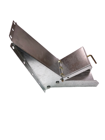 |
||||||||||||||||||||||
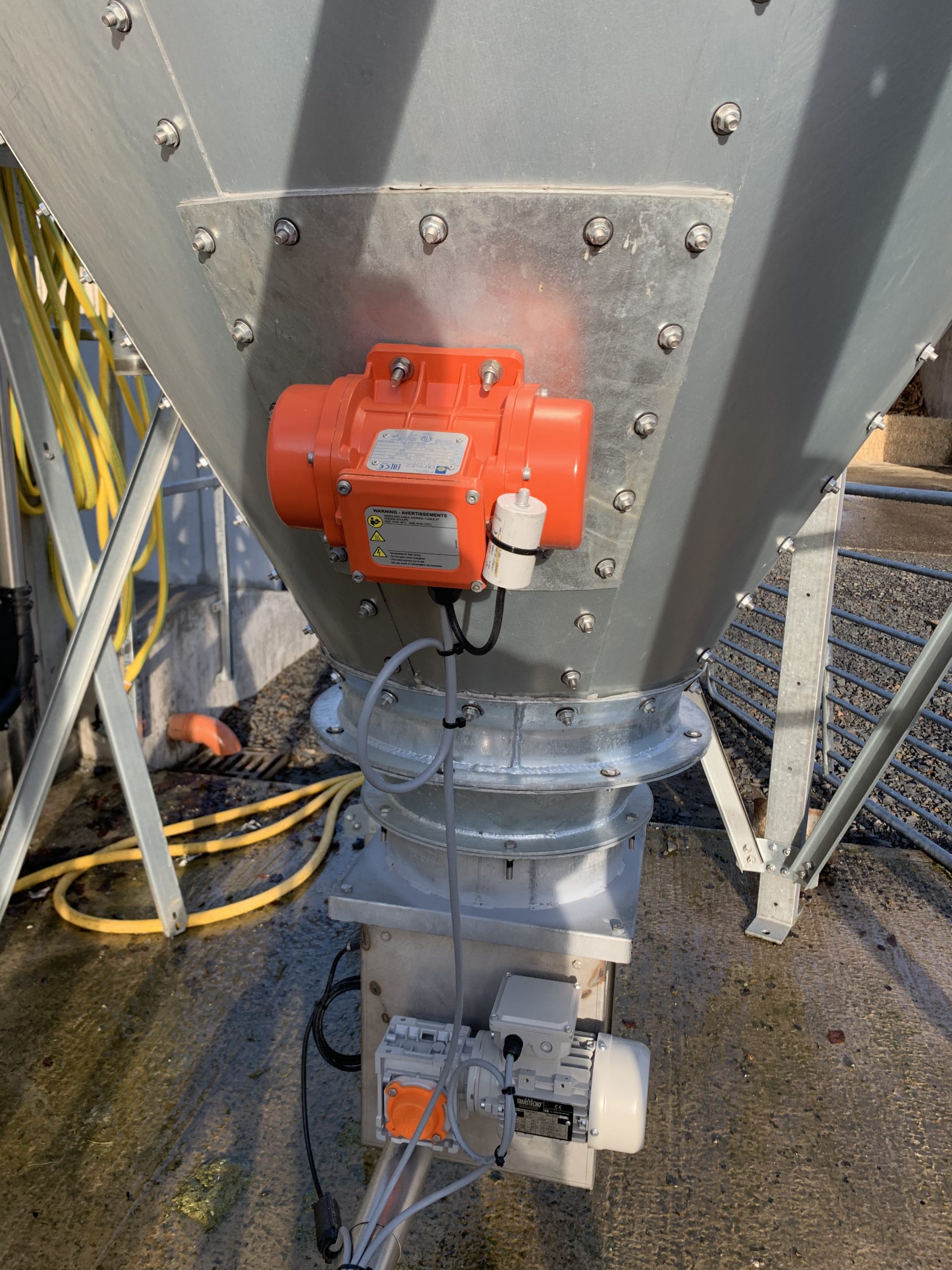
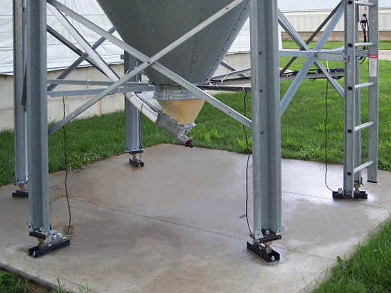
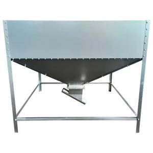
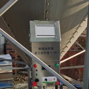
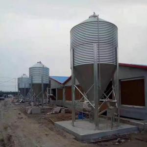
| Product Overview | The Feed Silo Manual Discharge Valve is a practical accessory for hopper-bottom feed silos and bulk feed bins. It provides a secondary gravity discharge point for collecting small quantities of stored feed without starting the main auger or automatic feed delivery system. The unit uses a manually operated slide gate combined with a discharge chute. When the gate is opened, feed flows by gravity from the silo hopper into a bucket, feed cart or other suitable container. When closed, the sliding plate shuts off the opening and can be configured with a locking provision to reduce accidental or unauthorized discharge. This simple mechanical design is well suited to commercial pig farms, poultry farms, cattle facilities, livestock breeding projects and feed-storage systems where operators occasionally need direct access to bulk feed for sampling, manual feeding, maintenance or small-volume distribution. |
||||||||||||||||||||||
| Key Features |
|
||||||||||||||||||||||
| Structural Components |
|
||||||||||||||||||||||
| Working Principle | The valve is installed on the sloping hopper section of a compatible feed silo. Stored feed naturally moves downward under gravity toward the hopper outlet area. When an operator raises or moves the manual slide gate, a secondary discharge opening is exposed and a controlled quantity of feed flows through the chute into a receiving container. Closing the gate blocks the opening and stops the flow. The valve is intended primarily for occasional small-volume discharge, sampling or bucket filling. It should not be treated as the primary silo unloading outlet unless the silo and valve system have been specifically engineered for that duty. |
||||||||||||||||||||||
| Technical Specifications |
|
||||||||||||||||||||||
| Applications |
|
||||||||||||||||||||||
| Customization Options | The Feed Silo Manual Discharge Valve can be configured according to silo diameter, hopper angle, hopper panel geometry, feed type and required discharge arrangement. Available options may include valve opening dimensions, chute length, chute angle, handle configuration, locking arrangement, mounting plate geometry, corrosion-resistant surface treatment and supplied installation hardware. For complete livestock projects, the valve can be coordinated with feed silos, auger systems, flexible feed conveyors, feed bins and steel structure farm buildings according to project requirements. |
||||||||||||||||||||||
| Installation & Maintenance | Before installation, the feed silo must be empty and secured against accidental filling or material movement. The valve position should be selected according to the silo manufacturer's structural requirements and should avoid hopper panel seams, braces or other areas that could interfere with installation. A mounting template can be used to mark the hopper panel. The opening is then cut with a suitable metal-cutting tool, mounting holes are drilled, and the slide-gate assembly is bolted to the silo with sealing material around the joint. Grinding or thermal cutting methods that damage galvanized coatings should be avoided. After installation, check that the slide moves freely, the chute is securely fastened and the locking mechanism aligns correctly. During routine maintenance, remove accumulated feed dust, inspect bolts and seals, and check the gate and guide rails for wear or deformation. Operators should never place hands or arms inside a loaded feed silo through the discharge opening because collapsing or bridging feed can create a serious engulfment hazard. |
||||||||||||||||||||||
| Project Cases | On commercial pig and poultry farms, a manual hopper discharge valve can provide a convenient secondary outlet beside the main automatic feed system. Farm staff can draw small quantities of feed for nursery pens, sick-animal care, feed sampling or equipment checks without operating the complete auger line. For new feed-storage projects, the valve position can be planned together with the silo foundation, access area, feed conveyor route and farm service road. Retrofit configurations can also be developed for compatible existing hopper-bottom bins after the silo structure and hopper geometry have been confirmed. |
||||||||||||||||||||||
| Product FAQ | Q: What is a feed silo manual discharge valve used for? A: It provides direct access to small quantities of feed from a hopper-bottom silo without operating the main auger or automated feed delivery system. Q: Can it be installed on an existing feed silo? A: Yes. Retrofit installation is possible on compatible hopper-bottom silos after hopper geometry, structural condition and installation position have been confirmed. Q: Is electrical power required? A: No. The standard configuration uses a hand-operated slide gate and gravity feed flow. Q: Can the valve be locked? A: A lockable slide-gate configuration is available to help prevent accidental or unauthorized discharge. Q: Is it suitable as the main silo outlet? A: It is primarily intended for occasional small-volume discharge. The main unloading system should remain the normal outlet unless the complete silo system is specifically engineered otherwise. Q: Can it handle different types of livestock feed? A: It is suitable for free-flowing feed materials. Compatibility with unusually large pellets, fibrous feed or materials with poor flow characteristics should be confirmed before ordering. Q: What information is required for quotation? A: Recommended information includes silo diameter, hopper angle, hopper material, feed type, required discharge opening, chute direction and photographs or drawings of the installation area. |
||||||||||||||||||||||
| Product Gallery | |
- Home
-
Products
- Pig Farming Equipment
- Cattle Farming Equipment
- Sheep & Goat Farming Equipment
- Poultry Farming Equipment
- Feeding & Drinking Systems
- Veterinary & Breeding Equipment
- Testing & Diagnostic Equipment
- Cleaning & Biosecurity Equipment
- Climate Control Equipment
- Livestock Weighing Equipment
- Manure & Waste Management
- Farm Transport & Handling
-
Solutions
- Pig Farm Solutions
- Dairy Farm Solutions
- Beef Cattle Farm Solutions
- Sheep & Goat Farm Solutions
- Layer Farm Solutions
- Broiler Farm Solutions
- Feeding & Drinking System Solutions
- Climate Control Solutions
- Biosecurity & Disinfection Solutions
- Manure & Waste Management
- Smart Farming Solutions
- Farm Renovation and Upgrade Solutions
- Partners
- Projects
- Resources
- News
- About Us
- Contact
Comments & Inquiries
Leave your questions or requirements below. We will reply as soon as possible.