
| Product Showcase | Content | ||||||||||||||
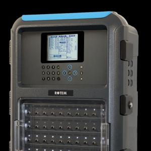
| Product Name | 0–10V Modulating Brooder Controller | ||||||||||||||
| Product Image | 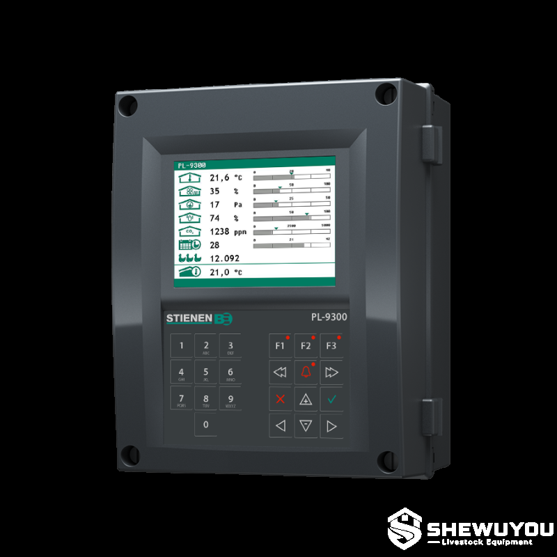 |
||||||||||||||
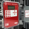
| Product Overview | The 0–10V Modulating Brooder Controller is designed for proportional control of compatible brooder heating equipment in commercial poultry houses. By using a 0–10V control signal, heating output can be adjusted progressively according to temperature demand, supporting stable brooding conditions and efficient climate management. | ||||||||||||||
| Key Features |
|
||||||||||||||
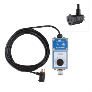
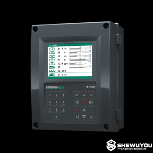
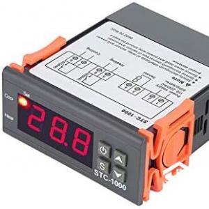
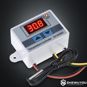
| Structural Components | A typical system consists of a controller, temperature sensing components, programmable control logic and a 0–10V analog output connected to a compatible modulating brooder heater. Additional control inputs or outputs may be included depending on the complete climate-control system. | ||||||||||||||
| Working Principle / Structural Principle | The temperature sensor measures the environmental temperature in the brooding area. The controller compares the measured value with the programmed temperature requirement and adjusts the 0–10V output accordingly. A higher control signal can command greater heating output, while a lower signal reduces heating intensity. This proportional operating principle allows the brooder to respond continuously to changing heat demand rather than relying only on simple on/off switching. |
||||||||||||||
| Technical Specifications |
|
||||||||||||||
| Applications |
|
||||||||||||||
| Customization Options | The controller can be configured according to the selected brooder heater, temperature sensor arrangement and overall climate-control system. Electrical configuration, control functions and installation requirements can be customized according to project requirements. For complete poultry farm projects, the control strategy can be designed according to local climate, building insulation, house structure and farm management conditions. |
||||||||||||||
| Installation & Maintenance | Install the controller in a dry and protected service location with convenient access for operation and maintenance. Connect the temperature sensor and 0–10V output according to the approved electrical wiring diagram. Position temperature sensors where they can accurately represent the brooding environment and avoid direct heat sources. Before commissioning, verify sensor readings, control settings and the response of the connected brooder heater. Regularly inspect wiring, terminals, sensor connections and enclosure condition. Follow applicable electrical standards and the manufacturer's technical instructions during installation and service. |
||||||||||||||
| Product FAQ |
Q: What is a 0–10V modulating brooder controller? Q: What is the benefit of modulating control? Q: Can it be integrated into an automated poultry house? Q: Can the controller be customized? |
||||||||||||||
| Product Gallery | |
- Home
-
Products
- Pig Farming Equipment
- Cattle Farming Equipment
- Sheep & Goat Farming Equipment
- Poultry Farming Equipment
- Feeding & Drinking Systems
- Veterinary & Breeding Equipment
- Testing & Diagnostic Equipment
- Cleaning & Biosecurity Equipment
- Climate Control Equipment
- Livestock Weighing Equipment
- Manure & Waste Management
- Farm Transport & Handling
-
Solutions
- Pig Farm Solutions
- Dairy Farm Solutions
- Beef Cattle Farm Solutions
- Sheep & Goat Farm Solutions
- Layer Farm Solutions
- Broiler Farm Solutions
- Feeding & Drinking System Solutions
- Climate Control Solutions
- Biosecurity & Disinfection Solutions
- Manure & Waste Management
- Smart Farming Solutions
- Farm Renovation and Upgrade Solutions
- Partners
- Projects
- Resources
- News
- About Us
- Contact
Comments & Inquiries
Leave your questions or requirements below. We will reply as soon as possible.