

| Product Showcase | Content |
|---|---|
| Product Name | Manure Slurry Ball Check Valve |
| Product Image |
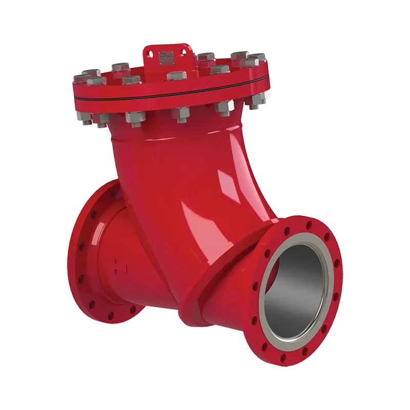 |
| Product Overview | The Manure Slurry Ball Check Valve is an automatic non-return valve for pumped livestock waste pipelines. Installed in the discharge line, it permits slurry to move toward a storage tank or treatment facility and closes when reverse pressure develops. Its simple ball-and-seat mechanism is suited to properly designed lines handling liquid pig manure and suspended solids. It can be incorporated into pump rooms serving commercial pig farms and steel structure livestock buildings. |
| Key Features |
|
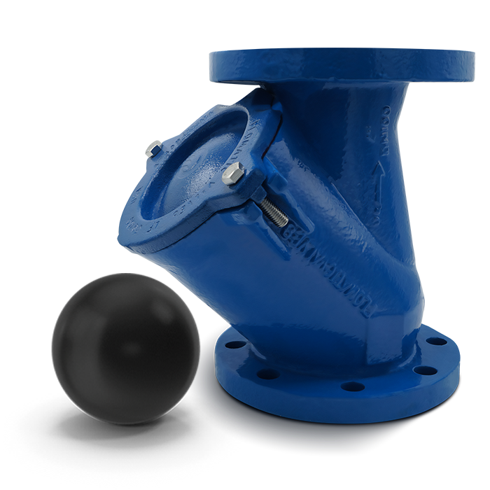
| Structural Components | A typical assembly includes a valve body, internal ball, valve seat, inlet and outlet connections, and a cover or access arrangement where specified. Replaceable wear and sealing components may be available according to the selected design. Material selection should consider slurry solids, corrosion exposure and the required service life. |
| Working Principle | Forward flow lifts the ball away from its seat and carries slurry through the valve. When the pump stops or downstream pressure becomes greater than upstream pressure, the ball returns to the seat and restricts reverse flow. The operating position and minimum flow required for reliable opening depend on the chosen valve design. |
| Technical Specifications |
|
| Applications | Suitable for selected manure pump discharge lines, pig slurry transfer stations, storage tank feed pipelines and farm wastewater handling systems. It may be used with submersible or dry-installed manure pumps when the valve is correctly sized for the pump duty and expected solids. |
| Customization Options | Connection size, pressure class, body coating, ball material, seat material and access arrangement can be reviewed against the project specification. Valve placement can be coordinated with the pump, isolation valves, pipe supports and maintenance clearance in a new pig farm construction or retrofit project. |
| Installation & Maintenance | Install in the indicated flow direction and only in an orientation approved for the selected model. Support adjoining pipework independently and leave access for inspection. Provide appropriate isolation so the valve can be depressurized before its cover is opened. During maintenance, check the ball, seat, internal passage and seals for wear or trapped debris; replace damaged components as required. |
| Product FAQ |
Does this valve need a motor or control signal? Can it serve as a manual shut-off valve? What information is needed for selection? |
| Product Gallery |
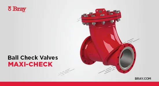
Illustrative reference images: Bray and Flomatic. Supplied valve materials, connections and configuration may differ. |
- Home
-
Products
- Pig Farming Equipment
- Cattle Farming Equipment
- Sheep & Goat Farming Equipment
- Poultry Farming Equipment
- Feeding & Drinking Systems
- Veterinary & Breeding Equipment
- Testing & Diagnostic Equipment
- Cleaning & Biosecurity Equipment
- Climate Control Equipment
- Livestock Weighing Equipment
- Manure & Waste Management
- Farm Transport & Handling
-
Solutions
- Pig Farm Solutions
- Dairy Farm Solutions
- Beef Cattle Farm Solutions
- Sheep & Goat Farm Solutions
- Layer Farm Solutions
- Broiler Farm Solutions
- Feeding & Drinking System Solutions
- Climate Control Solutions
- Biosecurity & Disinfection Solutions
- Manure & Waste Management
- Smart Farming Solutions
- Farm Renovation and Upgrade Solutions
- Partners
- Projects
- Resources
- News
- About Us
- Contact


Comments & Inquiries
Leave your questions or requirements below. We will reply as soon as possible.