



| Product Showcase | Content |
|---|---|
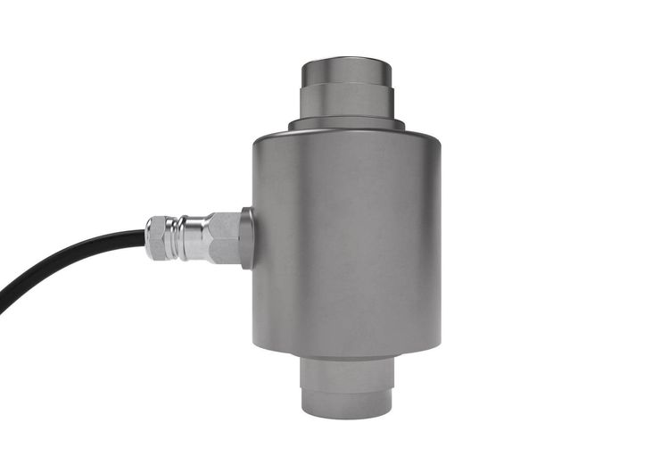
| Product Name | Column Compression Load Cell |
| Product Image |
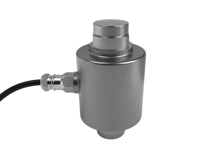 Reference product image; the supplied model is subject to the approved specification. |
| Product Overview | A column compression load cell measures high vertical loads transferred through a defined support point. It is suited to engineered weighing systems for feed silos, storage vessels, large platforms and agricultural vehicle scales. In commercial pig farm construction, the sensor can be incorporated beneath silo legs or heavy-duty weighing structures when the foundations, steel support frame and mounting assemblies are designed as a complete system. |
| Key Features |
|
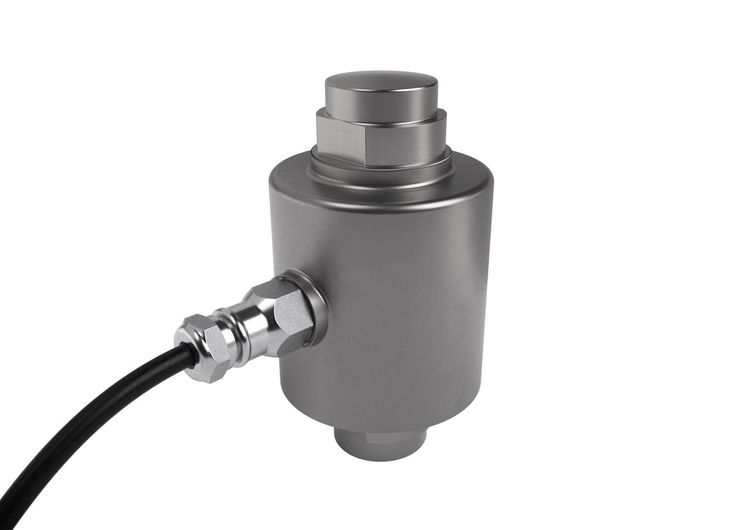
| Structural Components | A typical assembly consists of a machined compression column, bonded strain gauges, protected sensing area, loading surfaces and a shielded signal cable. The complete installation may also include upper and lower cups or mounting plates, lateral restraints, uplift protection, a junction box and a weighing indicator. Mounting components must match the selected sensor and the structural design. |
| Working Principle | A vertical load compresses the column by a small, controlled amount. Strain gauges detect the resulting deformation and produce an electrical signal proportional to the applied force. In a multi-support installation, the signals are combined and calibrated by the weighing system to determine the load on the platform or vessel. Proper alignment and freedom from unintended structural contact are essential to measurement accuracy. |
| Technical Specifications |
|
| Applications | Applications include feed silo inventory measurement, bulk ingredient tanks, high-capacity agricultural platforms and vehicle weighing systems serving livestock facilities. For a pig farm feed storage project, the load cells can provide weight data for stock monitoring when installed beneath an appropriately engineered silo structure. Smaller animal crates and bench scales generally require a different sensor capacity and mounting arrangement. |
| Customization Options | Capacity, sealing, cable length, mounting assemblies, junction box and indicator interface can be selected according to project requirements. Silo-leg brackets, protective covers and cable routes can be designed around the customer's foundation and steel structure drawings, site exposure and local climate. Final details are confirmed through technical review and an approved quotation. |
| Installation & Maintenance | Install each sensor between the specified upper and lower mounting components on sound, level structural supports. Check alignment and clearances, and use the approved restraints for lateral forces and uplift where required. Flexible connections may be needed on silo pipework so external forces do not bypass the weighing points. Route cables away from power lines and protect them from moisture, rodents and mechanical damage. Verify zero and calibration after installation, then inspect the mounts, restraints and wiring during scheduled maintenance. |
| Product FAQ |
Can it be used beneath a feed silo? How is the capacity selected? What information is needed for an enquiry? |
| Product Gallery |
  |
- Home
-
Products
- Pig Farming Equipment
- Cattle Farming Equipment
- Sheep & Goat Farming Equipment
- Poultry Farming Equipment
- Feeding & Drinking Systems
- Veterinary & Breeding Equipment
- Testing & Diagnostic Equipment
- Cleaning & Biosecurity Equipment
- Climate Control Equipment
- Livestock Weighing Equipment
- Manure & Waste Management
- Farm Transport & Handling
-
Solutions
- Pig Farm Solutions
- Dairy Farm Solutions
- Beef Cattle Farm Solutions
- Sheep & Goat Farm Solutions
- Layer Farm Solutions
- Broiler Farm Solutions
- Feeding & Drinking System Solutions
- Climate Control Solutions
- Biosecurity & Disinfection Solutions
- Manure & Waste Management
- Smart Farming Solutions
- Farm Renovation and Upgrade Solutions
- Partners
- Projects
- Resources
- News
- About Us
- Contact
Comments & Inquiries
Leave your questions or requirements below. We will reply as soon as possible.